We recently bought an EV. It came with a mobile charger with 120V and 240V connectors. When plugged into 120V, it will charge at a rate of 2-3 miles/hr (3-5 km/hr). With 240V, it can go as high as 30 miles/hr (~50km/h). But, where do you find a 240V-outlet in a house in the US?
Introduction
Many people think that houses in the US get only 120V electricity.This is not correct. Most of the electrical outlets will indeed have 120V, but high power devices, such as washer, driers, and ovens, run on 240V outlets. The power connection to a typical house is illustrated in Fig. 1.

Figure 1: The transformer circuit that reduces the grid voltage of 7200V down to 120/240V.
Typically, you would pull a wire from the center (neutral) terminal and one from the top or bottom terminals to the outlet. This will give 120V. However, the voltage from the bottom terminal to the top reads 240V. Some people will refer to this as two phases, but that is misleading. This is simply split output. The voltages are illustrated in Fig. 2.

Figure 2: The voltage plot across various terminals as a function of time.
So, this is the goal: build a 240V outlet for the EV.
For those who might think they can DIY this project, I have to give a set of very serious warnings:
- 240V is extremely dangerous, even deadly. If you have no experience with circuits involving high voltages, don’t attempt!
- This work is meant to be done by a certified electrician so that you can get a permit from your city.
- If you do a bad job, or use inappropriate materials or tools, you might damage your charger, your EV, or you may even burn down your house and kill your cat or dog!
I hope you will take the warnings above seriously.
If there is a chance of things going terribly wrong, why do I think I can do this myself? I think I can justify that. I was an electrician back in the days! I grew up in a country with the 220V voltage as the default. I built my first 220V circuit when I was 11. I have lots of experience with such voltages. I later became an electrical engineer and a physicist. So, I consider myself qualified for this task. I also purchased all the tools and good quality parts for the project!
Parts list
We will need all of the following parts listed in Tab. 1. Also see the image picker in Fig. 3 to see how they look.


Figure 3: Blueprint templates for LTspice circuit.

Figure 4: The electrical panel with three main lines entering from the bottom of the panel and snaking to the top.
On the left is the electrical panel with three main lines entering from the bottom of the panel and snaking to the top to connect to bus bars.
Some panels have the main breaker inside this panel, so the top part will still be live even if you shut that breaker off. My house has another service panel outside with a 200A circuit breaker. I shut off the power from that external breaker. So there is no chance of getting electrocuted.
If you measured the voltage voltage from the white(neutral) line to the black one or the red one, you will read 120V. If you measure across black and red, you will read 240V.
A single pole breaker connects to one of the black or red lines resulting in a 120V relative to the neutral line. A double pole circuit breaker will snap in with connections to red and black line, giving 240V. The neutral line will need to be connected separately for both single and double pole breakers. There are 4 available terminals to snap in a circuit breaker. I will use the top two to insert the 50A breaker.
The housing of the panel sits tightly between two studs. The bottom part is empty behind the dry wall. So it is reasonable to place the outlet right below the panel. There are punched circles at the bottom of the panel and you can knock them out with a flat screw driver and a mallet. The brackets are used to secure the cable to the electrical box and the panel. (not shown in the photos.)
It is obvious that there is a bunch of cables coming from the center at the bottom, so one needs to place the outlet a bit to the left. I first made a rough estimate of the position and started from my predicted center with a drywall cutting knife and made a horizontal cut to the left until I got to the stud. That fixes the x coordinate of the box since I will secure it to the stud on its left. I adjusted the y position by leaving a bit of space from the panel.
Once the box position is set, it is time for the wiring. The details of the circuit is discussed below. A 6-gage wire is not that easy to work with!
Connection diagram

Figure 5: The relevant connections are highlighted in orange color.
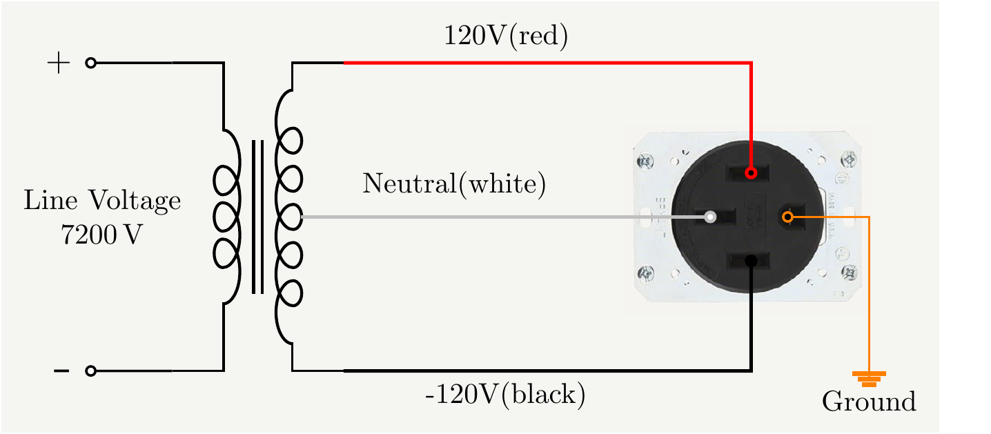
Figure 6: The connection diagram for the outlet. These receptacles typically have color names on the terminals so that you can coordinate the colors. The receptacle might be connecting its ground terminal to its metalic frame. Once screwed onto the electrical box, it will provide the grounding.

Figure 7: The final product! It looks like it requires a bit of cleaning, look at all of the finger prints! I think it still looks great!
It is very important to use the torque screw driver to torque the connections to the correct value.
- Bryant receptacle requires 75 in-lb, which is remarkably high. It is not quite possible to get to that value with a simple screw driver. If you don’t have a torque screw driver, you should halt the project until you get one.
- My circuit breaker screws required 45 in-lb.
- The panel connection itself requires 75 in-lb. This information was on the label on the panel, which was burried behind the cables.
- It is a good idea to pull on the wires strongly to make sure they don’t wiggle around and torque them again.
- The receptacle itself has its ground terminal connected to its metal frame. So the box will be grounded too once you screw the receptacle on it.
- Don’t forget to relax the torque screw driver down to zero.
Finally, I closed the lid of the panel, turn the main circuit breaker, measure all the voltages at the outlet. When everything checked out, I connected the charger. Its lights were all green. Finally, plug it in to the car, and it works! Mission accomplished!
PS: The EV manufacurer advises againt GFCI since it creates conflicts with the charger. They have their GFCI protection already inc the charger and the car.