Introduction
I wanted to build a heavy-duty bot that I can use for various purposes. I didn’t want to reinvent the wheel, and decided to look for a sneaky way of building one. My first idea was to use an old wheelchair base. I was planning to salvage the wheels and the motors only and purchase a motor driver unit. Then I came up with a very sneaky idea. What if I could hack into the joystick controller and use the whole system? This is the story of how I converted an old wheelchair I bought from Craigslist to a remote controlled bot for less than $10.
Parts
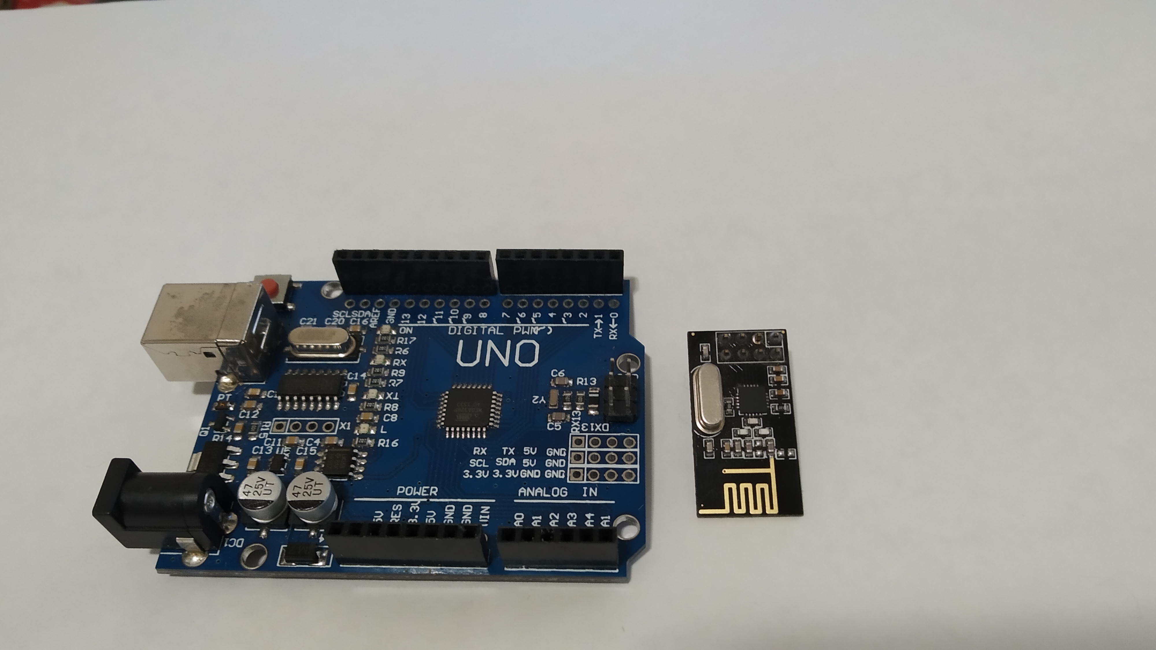
- 2x Arduino Uno boards
- 2x nrf24l01 transceivers
- one joystick, or joystick shield
- 2x 2.2K resistors
- 2x 33\(\mu\)F capacitor.
A quick tour
Browse through the images to see the parts used in the build. It is a set up based on a pair of Arduino Uno and nrf24l01. The idea is to fool the wheelchair controller to think that the signal it is receiving is coming from its own joystick. This won’t work for joysticks that use sophisticated digital communication with the controller. It will work for analog joysticks that simply produce two anolog signals to encode the position of the joystick knob.

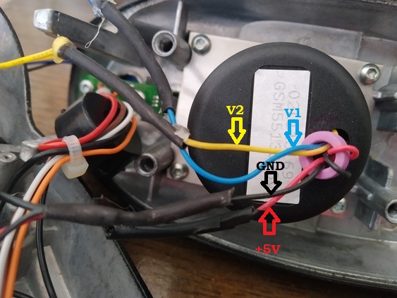
The joystick terminals
A resistive joystick encodes the position of its knob using to signals. I first probed the voltages on the four joystick terminals, two of which were simply the power lines (5V and ground). The other two lines encode the position. When the knob is at its center position, both lines showed 2.5V. If I push the knob all the way up(down) the voltage becomes 4V (1V). The same range applies to the other line when the knob is pushed all the way to the right or left. The trick here is to cut the two signal lines, and connect them to the output of Arduino.
Transmitting signals
nrf24l01 with Arduino uno is a great and very cheap method to send signals. We want to have a hand-held unit with a joystick and send the position of the joystick to the receiver. The great thing is that there is a shield for that! There is no soldering involved on the transmitter side, just drop in the shield on top of Uno. Although you won’t need to worry about the connections, they are described the code as well. You can find the code in my repository or copy it below.
//////////////////////////////////////////////////////////////////////////////////////////////////////////////////////
// Find details: https://tetraquarkbeta.netlify.app/post/wheelchair/wheelchair/
// A simple code to transmit joystick x and y values with Arduino Uno and nrf24l01
// get the librarry here: https://github.com/nRF24/RF24
// will work with the "arduino joystick shield with nrf24l01" You can find it at Ebay
// NRF Pin    Arduino Pin
//   Vcc         3.3V       DO NOT connect to 5V, it may damage the radio unit!
//   CS          10
//   MOSI        11
//   GND         GND
//   CE           9
//   CSN         10
//   SCK         13
//   MISO        12
// Note that CE and CS pins can be changed, if needed.
#include <SPI.h>
#include <nRF24L01.h>
#include <RF24.h>
#define CE_PIN 9    // these are the default connections for the joystick shield
#define CSN_PIN 10  // these are the default connections for the joystick shield
#define JOYSTICK_X A0     /// Connect Joystick output 1 to A0
#define JOYSTICK_Y A1     /// Connect Joystick output 1 to A1
const uint64_t pipe = 0xE8E8F0F0E1LL;
RF24 radio(CE_PIN, CSN_PIN);
int joystick[2];
void setup()
{
Serial.begin(9600);
radio.begin();
radio.openWritingPipe(pipe);
}
void loop()
{
joystick[0] = analogRead(JOYSTICK_X);joystick[1] = analogRead(JOYSTICK_Y);
radio.write( joystick, sizeof(joystick) );
Serial.print("Sending:  X="); Serial.print(joystick[0]); Serial.print("; Y="); Serial.println(joystick[1]);
}
/////////////////////////////////////////////////////////////////////////////////////////////////////////////////////| NRF | Arduino |
|---|---|
| Vcc | 3.3V* |
| CS | 10 |
| MOSI | 11 |
| GND | GND |
| CE | 9 |
| SCK | 13 |
| MISO | 12 |
| Joystick | Arduino |
|---|---|
| Vcc | 5V |
| GND | GND |
| Output 1 | A0 |
| Output 2 | A1 |
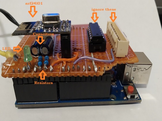
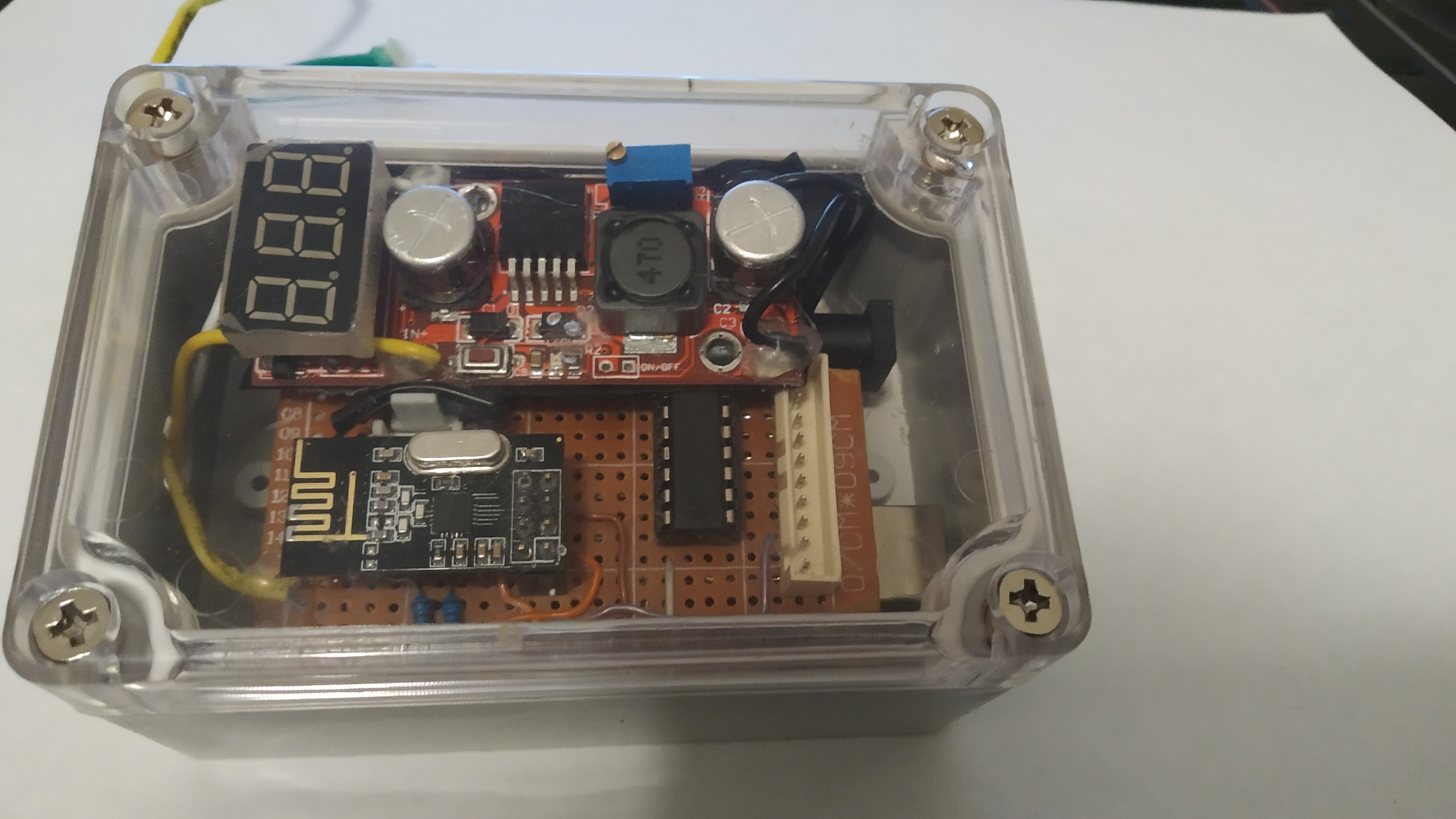
Receiving signals
Find the code in my repository or copy it below.
// Find details: https://tetraquarkbeta.netlify.app/post/wheelchair/wheelchair/
//A simple code to receive joystick x and y values with Arduino Uno and nrf24l01
// and to convert the values to Voltages using PWM (2.2K resistor and 33uF capacitor as a low pass filter will do the trick)
// note the CS and CE pin connections
// NRF Pin    Arduino Pin
//   Vcc         3.3V       DO NOT connect to 5V, it will damage the transmittet unit!
//   CS          8
//   MOSI        11
//   GND         GND
//   CE          7
//   SCK         13
//   MISO        12
// Note that CE and CS pins can be changed, if needed.
#include <SPI.h>
#include <nRF24L01.h>
#include <RF24.h>
#define CE_PIN 7
#define CSN_PIN 8
const uint64_t pipe = 0xE8E8F0F0E1LL;
RF24 radio(CE_PIN, CSN_PIN);
int joystick[2];// will store joystick doublet: first entry is the X value, second is the Y value
int lout= 3;// Will light up an LED when signal is received-very useful for debugging
int yout= 5; //PWM output for X value
int xout= 6;//PWM output for Y value


float central_valuex =  511.0; // this should be 512 theoretically but it may deviate from it a bit
float central_valuey =  502.0; // this should be 512 theoretically but it may deviate from it a bit

/// Joystick values are 10 bit numbers ranging from 0-1023
/// We will map these numbers a range so that when converted to voltage we get Vmin and Vmax
 //Vmax=4V for this example. We also assume center voltage is 2.5. The voltage will range from 1V to 4V in this example, i.e 1.5V swing
float Vmax=4.00;
float mindelta=10;// incoming joystick values may fluctuate a bit and more importantly as you try move the
// joystick along one axis only it may move on the other axis a bit as well. We will put a threshold for
// minimum deviation to clean out unintentional movement


int debugmode=1; /// use this to turn serial commumication on and off

int joyx;//the number to send to the PWM output. Min value is dictated by Vmin, max is by Vmax
int joyy;
void setup()
{
  pinMode(lout, OUTPUT);
     analogWrite(lout,0); ;
  Serial.begin(9600);
  delay(100);
  Serial.println("Nrf24L01 Receiver Starting");
  radio.begin();
  radio.openReadingPipe(1,pipe);
  radio.startListening();
}

void loop()
{
  if(radio.available())
    {
         analogWrite(lout,255);
      radio.read( joystick, sizeof(joystick) );
      /// calculate joyx and joyy
      if (abs(joystick[0]-central_valuex)<mindelta)
      {joyx=128;}// if the joystickx did not deviate enough from mid point set output to 128, which is 2.5V
      else{joyx=128+127*(joystick[0]-central_valuex)*((Vmax-2.5)/2.5)/(1023-central_valuex);}

      if (abs(joystick[1]-central_valuey)<mindelta)
      {joyy=128;}// if the joysticky did not deviate enough from mid point set output to 128, which is 2.5V
          else{joyy=128+127*(joystick[1]-central_valuey)*((Vmax-2.5)/2.5)/(1023-central_valuey);}

      analogWrite(xout, joyx);analogWrite(yout, joyy); // send the final results to the ports
      if(debugmode==1){
      //Serial.print("Received: X=");Serial.print(joystick[0]); Serial.print("; Y=");Serial.print(joystick[1]);
      Serial.print("; Converted to: Xpwm=");Serial.print(joyx);Serial.print("; Ypwm=");Serial.println(joyy);
      }
    }
    else {delay(300);Serial.println("No radio");   analogWrite(lout,0); ;analogWrite(yout, 128); analogWrite(xout, 128);}//wait 0.2 sec before deciding there is no radio
}
As we are going to convert the received signals to analog, the receiver requires a bit of soldering work. The connections are very simple and they are described in the code.

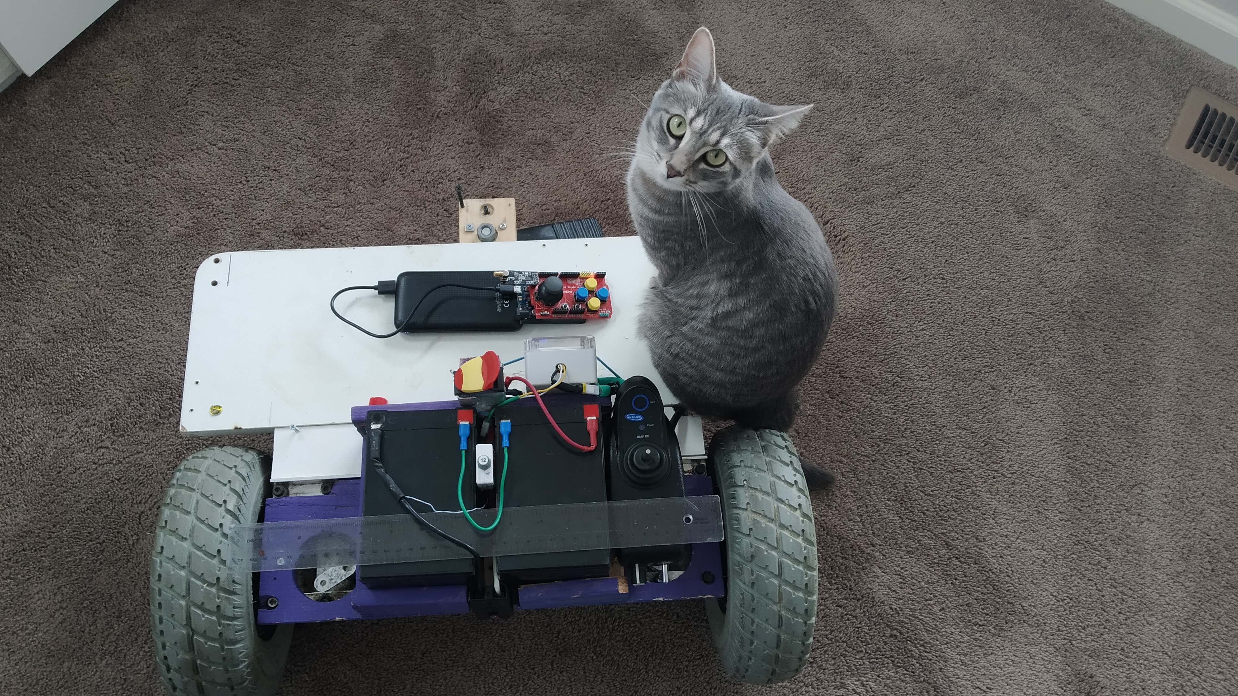
Putting it all together
In principle one can keep the wheelchair as is, at least the base of it. However, I wanted to have something a bit smaller, and I kept the controller unit, the joystick and the motors&wheels. I built an aluminum frame with a wooden platform and used a pair of relatively small batteries. I made it all modular so that I can easily remove the batteries, or the circuit for easier transportation. See below for the finished bot, which has become my cat’s favorite spot. It is a 3-wheeler with a caster wheel at the back. I located all the heavy parts close to the front wheel axis to maximize traction. I also left a large space at the back for a laptop. I am planning to make this autonomous!