Real coils are not purely imaginary
LIGO, coils
Practical coils
In order to build a predictive model, it is essential to include various aspects of real coils which deviate from idealized coils. First of all, it is wound with wires of finite resistance, and therefore there is a resistive component to it. Wires stacked together also cause a capacitive effect. Overall, a practical coil can be modeled as shown in Figure 1.
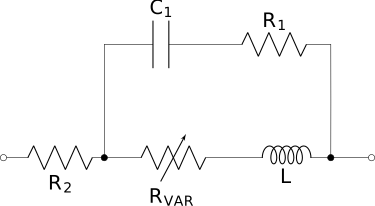
\(R_\text{VAR}\) in Figure 1 represents the skin effect, and it is given by
\[\begin{eqnarray} R_\text{VAR}=k \sqrt{f} \label{eq:skindepth}, \end{eqnarray}\]
where \(k\) is a constant we will extract from manufacturer data. We also analyze CoilCraft’s product data sheet, remove suspected data points and use regression to estimate the parameters of the practical coils that we use in the optimization process. The most significant deviation from an ideal coil is the serial resistance, \(R_2\), and we can set our expectations about it without even looking at the data. The inductance of a coil is proportional to the square of the number of turns. This simply follows from the fact that the field created by a each turn passes through every other turn as well, i.e., the interaction is \(\propto N(N-1)\sim N^2\). The length of the wire used in the coil is proportional to the number of turns at the first order (a small quadratic order term appears as the turn diameter increases with more turns.) Overall we can expect: \[\begin{eqnarray} R_2\propto N \propto \sqrt{L}\label{eq:r2prop}. \end{eqnarray}\] We can also argue that \(k\) is linear function of the magnetic field, which inturn proportional to the inductance. Therefore, if I was forced to make a prediction, I would predict the following relation:
\[\begin{eqnarray} k \propto L\label{eq:kprop}. \end{eqnarray}\]
Manufacturers tabulate and publish these parameters. We will use the data from CoilCraft, as shown in Figure 2.
Let’s look for some trends and outliers.
After removing the outlier points, we can check if the predictions in Eqs. \(\ref{eq:r2prop}\) and \(\ref{eq:kprop}\) hold by doing a scatter plot and a linear fit as seen in Figure 5.
Practical capacitors
In the zoo of capacitors, things look similar. Figure Figure 9 shows the equivalent circuit for a practical capacitor.

TDK has a note on ceramic capacitors as shown in Figure 10.